LABOCA - Das APEX-Facility-Kamera

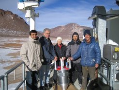
Von links nach rechts: N. Jethava, W. Esch, G. Lundershausen, G. Siringo und E. Kreysa.
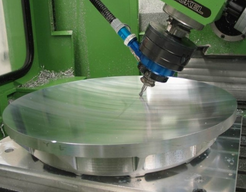
In der Mitte: der LABOCA-Kryostat - installationsbereit.
LABOCA is the first facility direct detection camera developed for the APEX telescope. It was installed in late 2006 and commissioned in 2007. As the receiver workhorse for APEX, a large variety of science cases has been successfully addressed with LABOCA.
Layout

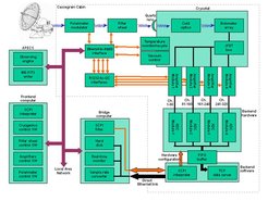
The LABOCA facility instrument is a bolometric continuum receiver made of 295 semi-conducting composite bolometers. The diagram below presents an overview about all sub-systems and devices of the receiver.
Detector Array

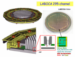
CAD drawings showing the assembling at the focal plane. The bolometer array is mounted inside a copper ring, under a monolithic array of conical horn antennas and above a reflector at a quarter wavelength distance. Right, top: a picture of the "naked" LABOCA array. Right, bottom: design scheme of a single bolometer.
The bolometer array of LABOCA is made of 295 composite bolometers, arranged in a hexagonal layout – a center channel surrounded by 9 concentric hexagons. Unstructured silicon nitride membranes, micro-machined on a single 4-inch silicon wafer, carry the composite bolometers and thus form an array of detectors. The membranes are only 0.4 µm thick and are coated with a thin titanium film, absorbing the incoming radiation. Neutron-transmutation-doped (NTD) germanium chips (called thermistors), soldered to the membranes, detect the temperature rise due to the absorption of radiation.

Optics

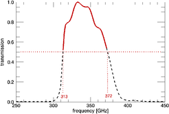
The optical system consists of a series of active and flat mirrors followed by a lens, acting as cryostat window. A set of in-house fabricated cold filters define the spectral passband, a monolithic array of conical horn antennas in front of the bolometer wafer, acts as beam-defining element. LABOCA is designed for observations in the 870 µm sub-millimeter atmospheric window. Since bolometers show a broad band response a set of filters, mounted on the liquid nitrogen and liquid helium shields, define the spectral pass-band. As displayed below, the transmission is centered at a wavelength of 870 µm (345 GHz) with a bandpass of 150 µm (60 GHz), well matched to the atmospheric transmission to avoid sky noise contributions. The circular wave guides embedded in the conical horn antennas act as high-pass filters providing a well defined cut-off at the low frequency side of the passband.


Readout

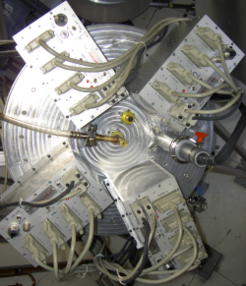
The readout voltages of the thermistors are channelled to the outside of the cryostat along 12 flat cables made of Manganin wires on Kapton substrate, thereby passing low-noise, unity gain JFET amplifiers at liquid nitrogen temperature. The signals are distributed to four amplification units, providing 80 channels each. 25 of these channels are used for technical purposes like noise monitoring and calibrations, while the rest reads out the bolometers. The amplification units provide an AC current bias to the bolometers and perform real time demodulation of the 320 signals. This electronic scheme is fundamental for the stability of the post-detection signals at low frequencies. The AC bias frequency is provided by the data acquisition system as a sub-multiple of the sampling frequency (usually set to 1 kHz) thus synchronizing the bias to the data sampling. Microprocessors in each amplification unit provide the digital interface, with full remote control via Ethernet. To avoid saturation problems, DC-offsets are removed at the beginning of an observation. These offsets are stored to recover them during the data reduction process. The in total 320 channels are digitized by four 16 bit multifunction DAQ PCI boards mounted into an industrial computer. Before reaching the telescope's control software, the data (about 4 MB/s) are digitally filtered and down sampled to 25-50 Hz in real time by the so-called “bridge” computer. The data acquisition software provides a SCPI (Standard Commands for Programmable Instrumentation) interface to the APEX control software, used to set-up the hardware, and a TCP data server, for the data output. The software is capable of monitoring the temperatures, controlling the sorption cooler and the calibration unit.
Performance
 weiten Empfindlichkeitsintervallen.")
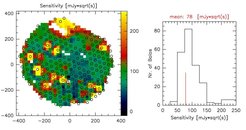
During the science verification run in May 2007 the mean point-source sensitivity of LABOCA has been determined, based on 250 fully functional pixels.al','sans-serif'; colorAn rms weighted average pixel sensitivity of 78 mJy·sqrt(s) was measured by a residual sky noise filtering process. In typical observing conditions of 1 mm of precipitable water vapour this translates into a mapping speed of 1 square degree per hour with a noise level of 40 mJy/beam. Without the sky noise filtering the mean pixel sensitivity was measured to be 120 mJy·sqrt(s). The sensitivity variations across the array (left figure in the plot below) are significant. To observe compact sources we make use of the best part of the field-of-view (FoV) instead of using the array center pixel. The noise behaviour for long integrations has been determined by a deep integration of 4 hours: The noise integrates down with sqrt(t), and finally reaches 2.5 mJy/beam (see figures).

