TFR – Time and Frequency Reference
Distributing time and frequency over long distances while providing an option that compensates for offsets.
High precision timing is crucial in radio-astronomical applications. Both the absolute time and, even more importantly, an accurate reference clock are essential, for instance when detecting and long-term analyzing the fast-rotating neutron stars called pulsars. GPS receivers are used as a source for absolute time, while the reference clock is usually generated by a hydrogen maser. Distributing these signals to the receiver systems, in particular with array-based telescopes, poses a major challenge. The synchronization of the single dishes is essential to correlating their individual data-streams.

That is where a Time and Frequency Reference system comes into play. The purpose of this system is not only to distribute time and frequency over long distances but also to provide an option that compensates for offsets caused by different cable lengths to the individual antennas.
TFR-Generator
The TFR-Generator is a unit that generates and distributes high precision reference signals (time and reference) over fiber optical cables. A 100 MHz input signal (usually derived from a hydrogen maser) is used to generate a GHz-carrier tone (typically around 1.75 GHz) on which the time input signal is modulated. Both signals (reference and modulated time) are then distributed via optical fiber .
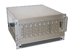
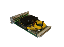
A TFR-Generator comes as a 19 inch slide-in (see Figure 2) carrying a TFR-Control and up to 9 TFR-TX units (see Figure 3). The purpose of the TFR-Control is to receive the reference signals and to perform all kinds of control and monitoring tasks for the TFR-Generator. The TFR-TX units modulate the time signal on a carrier tone to finally convert and distribute both signals (time and reference) fiber-optically. Each TFR-TX unit provides 8 output pairs resulting in a total of 72 outputs for the whole TFR-Generator.


TFR-Receiver

A TFR-Receiver (see Figure 4) is the unit that receives the time and frequency signals fiber-optically and converts them back to a copper-based digital signal. The optical power of the received fiber signals is detected and becomes available as an analog voltage signal. In addition, the TFR-Receiver contains a fiber-retro-reflector. It reflects a small amount of the received time signal back to the sender, which makes round-trip measurements possible.
Round-Trip Measurements

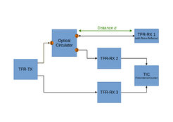
The block diagram below (see Figure 5) shows the basic concept of the round trip system. The idea behind this setup is to determine the propagation-delay that is created when a signal is distributed fiber-optically over a distance d. Therefore a standard TFR-TX unit is used to send the time signal to the TFR-RX 1 unit (usually located inside the astronomical receiver). The light returned by the retro-reflector inside is forwarded to TFR-RX 2 by an optical circulator. TFR-RX 3 directly receives the optical time signal from the TFR-TX unit and serves as a reference. The two signals are then compared by a time-interval-counter, where the calculated offset between the two signals represents twice the propagation-delay for distance d.


