Fast Fourier Transform Spectrometer
Back in 2003, spectrographs for radio astronomy were usually realized as analog filter-banks, acousto-optical spectrometers (AOS) or with the concept of a digital auto-correlation. At that time, the development of the first Fast Fourier Transform Spectrometer (FFTS) was launched at the MPIfR. The first concept made use of one of the upcoming commercial boards, initially designed for applications in “software defined radio”, that made on-board signal processing possible using a combination of analogue-digital-converter (ADC) and field programmable gate arrays (FPGA). The Fourier transformation itself was based on a rudimentary Fast Fourier Transform core (Gateware VHDL code) for the FPGA.
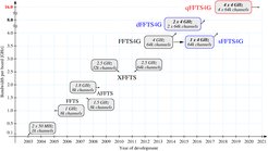
Since then the development of the FFTS progressed alongside the evolution of electronic devices, allowing to process broader bandwidths and higher channelization. The timeline of the developments is displayed in the figure, indicating the capabilities of just 50 MHz of bandwidth and 1024 spectral channels in the early phases to the most advanced spectrometers today.
 are in successful operation at various telescopes. The red box in the upper right corner marks our latest spectrometer development. The qFFTS4G is capable of analyzing four IF inputs, each with 4 GHz instantaneous bandwidth, in 4 x 64k spectral channels. Like the single input board sFFTS4G, the qFFTS4G also allows processing of IF signals in the 2nd Nyquist zone (4-8 GHz).")
Generally, the increase in bandwidth of modern SIS and HEB mixers, the new generations of multi-pixel heterodyne receiver arrays, or the requirement of operating in full polarization are driving the development of the FFT spectrometers, processing broader bandwidth with higher spectral resolution. The novel concept in the beginning and the evolution of the spectrometer design over the years position the developments at the forefront of R&D in signal processing. Nowadays these kinds of systems can be easily adapted to single and multi-beam receiver arrays and with standardized Ethernet interfaces. Even a combination of multiple boards forming an FFTS array can be realized by a common Ethernet switch.
New developments make use of novel RF-ADC technology allowing for direct intermediate frequency (IF) sampling and integrating these ADCs enables a development of much more compact back-end devices, much simpler IF systems without analog signal mixing, and enabled a more stable and cost-effective design.
With a variety of FFTS designs in use, partly specialized for different tasks, it became desirable to combine different types. Therefore, the FFTS control software was evolved alongside to support operating XFFTS, FFTS4G, dFFTS4G, sFFTS4G and theoretically qFFTS4G mixed within one system. Aside from improving and straightening initialization routines and configuration parameters, new synchronization procedures between multiple FFTS boards were developed, constantly comparing timestamps and phase counters to detect and correct mismatches more reliably.
Our developments like the dFFTS4G and sFFTS4G boards are operating successfully at APEX or SOFIA for years.