Digitizer and Packetizer
A full digital receiver and backend is the next evolutionary step in radio astronomical observatories that allows for easy diagnostic and maintenance and provides a robust and stable system. In particular, at low frequency bands, man-made radio frequency interference (RFI) either from our daily life gadgets or even internal digital electronics needs to be filtered out, this step is difficult to be realized with conventional analogue components. For this purpose a split architecture of a digitizer and packetizer module have been developed, that converts the analogue signal into a digital stream of structured data, and enables us to better mitigate and handle systematic effects in the signal chain of a radio-astronomical receiver systems.
In detail, the system is built of two different modules, a digitizer and a packetizer unit, with both having different functionality. The digitizer converts two analogue signals into time labelled digital signals, whereas the packetizer unit will distribute the signals in a pre-defined and grouped data format. Both modules can be physical separated by a few hundreds of meters.
The main hardware components of the digitizer are two analogue digital converters (ADC), a synthesizer, a field-programmable gate array (FPGA), and an optical fibre connector. The ADC converts the analogue signals, by sampling these simultaneously with a 1 pps signal and is locked onto the sampling frequency. The synthesizer provides the sampling frequency at the GHz regime, which is based on the 100 MHz reference clock. The FPGA, acts like a small processor, running at the reference clock rate and organizes the communication of the digitizer. The optical fibre connects the digitizer with the packetizer.
The main hardware components of the packetizer are a FPGA, a Raspberry Pi (RasPI), an optical fibre connector, and high speed Ethernet interfaces. The FPGA is running synchronized at an integer fraction of the sampling rate of the ADC, does the time labelling, some arithmetic, and restructures the data stream into many multi-cast groups. The Ethernet interfaces will connect the packetizer to a network infrastructure. The RasPI is the access point to the Digitizer & Packetizer-system and organizes the operation, the housekeeping and the overall communication.
Two versions of the digitalization modules have been development, a digitizer 1 / packetizer 1 as part of the MPIfR S-Band receiver system of the MeerKAT array, and a digitizer 2 and packetizer 2 prototype system providing larger bandwidth and higher data rates. Currently version 1 systems are operating in MeerKAT, Effelsberg, MPG-SKA Prototype Telescope, and the Thai National Radio Telescope (TNRT).

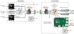
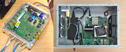
Digitizer 1 / Packetizer 1: Overview of the split architecture. The digitizer unit is located close to the receiver, separated from the packetizer unit, which will be installed in the telescope pedestal. They are connected via fiber link.


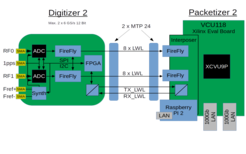
 and the Packetizer 2 (right).")
Comparison of different digitizer / packetizer versions. From left to right, setup used in MeerKAT, general options for version 1, general options for version 2.
| MeerKAT | EDD1 | EDD2 | |
|---|---|---|---|
| Hardware | Packetizer 1 + Digitizer 1 | Packetizer 1 + Digitizer 1 | Packetizer 2 + Digitizer 2 |
| FPGA | MKT | EDD | EDD2 |
| Sampling Frequency | 3.5 GHz | 2.6 / 3.5 / 4.0 GHz | 5.0 / 6.0 GHz |
| max Bandwidth | < 875 MHz | < 2000 MHz | < 3000 MHz |
| Decimation Factor | 2 | 1 / 2 / 4 / 8 / 16 | 1 / 2 / 4 / 8 / 16 / 32 |
| Sub-Band Filters | 5 | none | none |
| Ethernet Interfaces | 1 x 40 GbE | 2 x 40 GbE | 2 x 100 GbE |
| max. Bitrate | 1 x 35 Gbit/s | 2 x 35 Gbit/s | 2 x 96 Gbit/s |
| Bit Depth | 10 bit/sample | 8 / 10 / 12 bit/sample | 8 / 10 / 12 bit/sample |
| Polarisations | 2 | 2 | 2 |