
The AMBER instrument
Overview
The instrument is built for two or three beams from either the 8-meter VLT unit telescopes (UTs) or the 1.8-meter auxiliary telescopes (ATs). AMBER offers the means to perform high quality interferometric measurements and is able to reconstruct real images using phase closure techniques. With a spectral resolution of up to 10000 and a limiting magnitude of 14, the angular resolution is 2 mas in the K band. The excellent instrument stability allows a visibility accuracy of 10−3 to 10−4 for bright objects. The main scientific objectives are the investigation of disks and jets around Young Stellar Objects and Active Galactic Nuclei (AGN) at very high angular resolution.
 |
Object classes: hot exoplanets, formation and evolution of stars, extragalactic sources |
 |
Atmosphere |
|
Telescopes: ESO VLTI |
 |
Delay Lines ESO Delay Lines |
 |
Optics: Optics developed by the AMBER consortium |
 |
Spectrograph: Spectrograph developed by the AMBER consortium |
 |
Imaging sensor: HAWAII-1 |
 |
Electronics: Readout Electronics developed by our group |
 |
Instrument Control Software: AMBER Detector Control Software (DCS) developed by our group |
 |
Data Reduction Software: AMBER Data Reduction Software (DRS) |
Our Work
Our department was responsible for the detector subsystem, including data acquisition and control software. The detector development and successful integration of the detector subsystem for the AMBER instrument was one of the most important international projects of our division that has taken part in the last few years.
Readout-Electronics


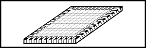
For the AMBER project, we used a precursor to our actual readout electronics that has been modified to the special requirements of the instrument. The AMBER spectrograph output illuminates well defined areas on the imaging sensor. There are four areas: three photometric channels and one interferometric channel. Each of these is 16 pixels wide, seperated by roughly 100 pixels containing no information. Depending on the selected spectral resolution, the channels are 25 to 512 pixels long. As a result, large areas of the imaging sensor are of no interest and will be ignored. To speed up the readout, unused pixels are clocked faster. The pixel clock frequency is switched between 500 kHz (slow) within the areas of interest and 10 MHz (fast) elsewhere. According to the separation of the channels the clock must be switched several times during the readout of one imaging sensor line. Within the fast clocked areas of the sensor no data is produced.
Software
The AMBER software consists of several modules, e.g., Observation Software (OS) and Detector Control System (DCS). These modules can be characterized by their functionality (detector specific, scientific imaging, etc.). The total software architecture is defined by ESO and provides specifications and implementation. The detector control system has been implemented in full at our institute.
The main development goal was to adapt the given implementation to comply with AMBER-specific requirements. One major task was the integration of the AMBER infrared camera into a software system that was developed for a completely different hardware. The main interfaces between the software system and the detector are the command interface and the data acquisition interface, both of which are parts of the DCS.
DCS (Detector Control Software)


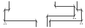
The software architecture of the DCS (see figure) has a modular structure. The software modules on the Local Control Unit (LCU) interact directly with the detector hardware electronics, whereas the modules on the Workstation WS mediate between modules on the LCU and the rest of the software system (e.g., OS).
The sequence of a typical observation run is as follows: An observer starts an observation block (OB). An observation block defines all necessary settings for an observation, for example, the position of the object, readout mode, integration time, number of requested images, etc. All values relevant for the camera are transferred to the DCS server (amdiracqServer) on the WS. This server sends commands to the command server (amdtcomIrcs) on the LCU, controls the data acquisition task (amdsdma) on the LCU and notifies the data transfer task (amdiracqDtt) on the WS of the current exposure.
Project Milestones
- Conceptual Design Review in January 1999
- Preliminary Design Review in February 2000
- Final Design Review in April 2001
- Preliminary Acceptance Europe in December 2003
- Integration at the ESO-VLTI on Paranal, Chile in April 2004
- Commissioning runs in May and September 2004
- Astronomical observations since 2005
- Detector upgrade September 2007