N3AR – The New 3 mm APEX Receiver
The N3AR is a single-pixel, dual polarization, sideband separating heterodyne receiver operating in the extended W-band frequency range (67 – 116 GHz; i.e. wavelength range around 3 mm).
N3AR is installed in the Cassegrain cabin of the Atacama Pathfinder EXperiment telescope (APEX), next to our A-MKIDS camera.
")

Specifications overview
RF bandwidth | 67 – 116 GHz |
IF bandwidth | 4 – 12 GHz, per polarization, per sideband |
Dual-color observations | Simultaneous observations with NFLASH-230 or SEPIA-345 possible |
Average noise temperature | 40 – 50 K |
Sideband separation | ≥ 15 dB |
Technology | Corrugated feedhorn |
Motivation
The initial idea to build the receiver came up in January 2023 during an Atacama Pathfinder Experiment telescope (APEX) conference at Ringberg castle, Germany.
Goal was that APEX – which was already regularly participating in VLBI observations e.g. with NFLASH-230 - also joins the Global-mm VLBI (GMVA) observations at 3 mm wavelength. Another important motivation was to perform simultaneous VLBI observations at 3 mm and shorter wavelength, and subsequently try to use the atmospheric frequency phase variations measured at 3 mm to improve the calibration of the observations at the shorter wavelength.
Additionally - outside of the time-slots of VLBI campaigns - the receiver should be usable for spectroscopic measurements in the extended W-band, e.g. during weather condition too bad for observations at higher frequencies (N3AR's motto: "I like clouds").
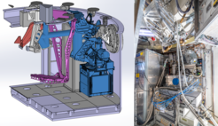
 CAD sketch of a cut-out of the APEX Cassegrain cabin with N3AR in blue; A-MKIDS M3 mirror and mountings in pink. (Right) Photo of N3AR during installation, still without mounted LOA (blue disk below the center of the photo is the protection cover of the RF window)")
History
Development of the receiver started in April 2023. To join VLBI observations as soon as possible, the receiver design relied heavily on already existing equipment in our institute and commercially available hardware. The design of the new ALMA band 2+3 receiver served as a basis for our receiver. The system was installed at APEX in September 2024, and participated in a first VLBI campaign just a few days later, from 11. – 14. October 2024. First successful, simultaneous, dual-color (3 mm and 1.3 mm) VLBI observations were performed from 19. – 22. November. Currently, the system is in its commissioning phase for spectroscopic observations.
Technology
Contrary to APEX' other receivers, N3AR does not use cooled mixers, e.g. SIS. It is based on cooled HEMT amplifiers and a first mixing-stage at ambient temperature. Because this makes the interiors of the cryostat quite simple, the complexity of the receiver is drastically reduced, making it more reliable, easier to use and maintain.
N3AR consists of a cryostat build in our institute, cooled by a Sumitomo RDK-415P cold head, two optics assemblies and an electronics rack, which also carries the cryostat (Figure 1 and Figure 2).
The „Upper Optics Assembly“ (UOA) is mounted to the Cassegrain cabin's ceiling and houses mainly the select-optics assembly to switch between single- and dual-color observations. The telescope beam either
- passes through the optics assembly untouched (single-color observations with NFLASH/SEPIA or any other (future) receiver in the A-cabin of APEX)
- is redirected towards N3AR by a flat mirror (single-color observations with N3AR), or
- is split up using a dichroics filter, which was fabricated in our institute (dual-color observations with N3AR and either NFLASH-230 or SEPIA-345); here, N3AR's beam is in reflection, whereas NFLASH/SEPIA's beam is in transmission.
The "Lower Optics Assembly" (LOA) is fixed to the cryostat and has motorized mirrors to direct the receiver beam towards calibration loads.
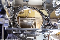
: Feedhorn on the left, connected to the OMT, 2 HEMTs separated by an isolator per polarization, and WR-10 waveguides:")

Inside the cryostat (Figure 3), the corrugated feedhorn, from Radiometer Physics GmbH (RPG), is connected to an Boifort Orthomode-Transducer, made in-house, which splits the polarizations. The wave of each polarization is then amplified by two HEMTs (manufacturer: Low Noise Factory), separated by an isolator from MicroHarmonics. The amplified signals are afterwards directed out of the cryostat, into a down-converter system, also made by RPG. The RPG-system incorporates RF- and IF-hybrids to separate the sidebands, as well as a quadrupler for the LO frequency generation. A synthesizer module from Virginia Diodes Inc., followed by a custom-made doubler stage, generates the driver frequency for the LO signal. The down-converter generates four IF signals (1 per polarization and sideband) in the range of 2 – 20 GHz. Two of these outputs can be split and directed to the VLBI digitizers. For spectroscopic observations, all four outputs are further processed by our modular IF processor (a copy of the NFLASH/SEPIA IF processor), which converts the two bands, 4 – 8 GHz and 8 – 12 GHz, to 0 – 4 GHz baseband. Each baseband signal is finally digitized by a channel of our dual-channel Fast-Fourier-Transform-Spectrometer cards (dFFTS).
Dichroics filter
A major challenge was the development of the dichroics filter for simultaneous observations with N3AR and either NFLASH-230 or SEPIA-345. The filter had to be a high-pass filter, because of optical paths of NFLASH and SEPIA and space considerations in the Cassegrain cabin.

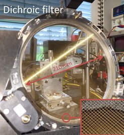
 Lab setup, inset: zoom-in of the cross-wired grids with sub-mm distance. (Below) Filter installed at APEX in the UOA.")


The final design (Figure 4) is based on two free-standing wire grids. Each grid has horizontally and vertically oriented, 20 µm thick wires, with a spacing between two adjacent wires of 500 µm (i.e. they are cross-wired grid, see zoom-in in Figure 4). The wires are winded in our institute onto circular frames with a free aperture (i.e. inner diameter) of ~210 mm.
The distance between the planes of the two cross-wired grids defines the transmission behavior of the filter and is in the range of 200 – 500 µm (Figure 5). The grid frames are connected to each other by springs, three screws push against these spring and define the distance. Currently (end of 2024), the spacing between the two grids is fixed to a position which yields best transmission at 258 GHz (i.e. the frequency of the NFLASH-230's VLBI observations in October). However, the grid frames are already equipped with motors to drive the screws remotely: our goal is a fully remote-controllable dichroics filter for transmitted frequencies between 200 – 400 GHz, to enable dual-color observations with best transmission over the whole RF bands of NFLASH-230 and SEPIA-345.
Calibration
For calibrating the receiver gain, the well-known Y-factor methods can be used. Another approach is to cross-check against known point sources at 3 mm wavelength.
For the Y-factor method, the receiver system incorporates three calibration loads at different temperatures: cold-load at ~50 K; ambient-load at ~290 K; hotter-load at ~350 K. The "cold-load" is realized by "looking back" onto an absorber inside the cryostat. The "hotter-load" consists of a heated, temperature-controlled, absorber-coated cone. All loads are made in the institute.