The U-Board
A closely coupled heterogeneous architecture

This development is part of the SFB 956 “Cosmic Cycle of Star Formation”, which investigates the complex interplay between star formation and its embedding interstellar medium (ISM). The DSP division is responsible for the work package D4 - Digital Signal Processing, which is a R&D package focusing on the exploration of new developments of digital signal processing techniques. A new readout system for the A-MKID camera at the new CCAT-prime telescope in Chile is developed. The U-Board combines all the requirements of such a system, the generation of coherent signals, signal acquisition, and powerful signal processing. The special architecture and design of the U-Board enables a broad range of application of the U-Board either as readout system or as signal generator for e.g. molecular spectroscopy in lab’s for which coherent signals are required.
Microwave Kinetic Inductance Detectors (MKID) are superconducting notch filter, whose resonance frequency changes dependent on the photon flux, usable as incoherent detectors. A single MKID pixel can be read out by generating a sinusoidal signal, called tone, at its resonance frequency and analyzing the phase and amplitude changes of the tone after it passed the MKID. The camera is built out of a number of MKID detectors and its frequency band that can be read out placing a tone in each of the resonances over the entire band. The phase of the read out tones is more sensitive to small changes of the resonance frequency of the MKIDs and is therefore a better choice than the amplitude. The readout system of the U-Board is taking this into account and archives high phase stability by a homodyne mixing scheme (up- and down-conversion with the same local oscillator).
 and the developer kit from NVIDIA, which includes the GPU module. The waveform is streamed from DDR4-memory directly to the DACs. The acquired waveform is processed by 16 parallel FFTs in the FPGA, which are combined into the resulting spectral bins on the GPU module. These are processed further into the reduced phase, which is sent out via Ethernet.")
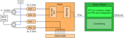
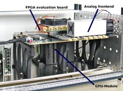
Figure: The heterodyne MKID readout system based on the U-Board platform. To cover the 4 GHz bandwidth two IQ mixers are used for up- and down-converting with the same local oscillator. It is split into the analog front-end on a custom PCB, the Xilinx evaluation board (housing the FPGA and DDR4-memory) and the developer kit from NVIDIA, which includes the GPU module. The waveform is streamed from DDR4-memory directly to the DACs. The acquired waveform is processed by 16 parallel FFTs in the FPGA, which are combined into the resulting spectral bins on the GPU module. These are processed further into the reduced phase, which is sent out via Ethernet.
The first prototype of the U-Board is based on an evaluation board from Xilinx (VCU118) in combination with the developer kit from NVIDIA for the Jetson Xavier AGX module. Both are connected via a designated PCIe connectors on boards. The FPGA/GPU combination is extended with a custom PCB that hosts the ADCs and DACs. The waveform is calculated on the GPU module with an inverse FFT. At this step the imperfection of the DACs and IQ mixers, which needs to be measured beforehand, are taken into account to optimize the sideband separation and therefore reduce the power injection into the array. The resulting waveform is stored in the DDR4-memory that is directly connected to the FPGA. This waveform is then streamed from the DDR4-memory to the DACs. The analog signal is mixed with a LO signal to generate the required tones for the readout of the MKID detectors.