N3AR – The New 3 mm APEX Receiver
N3AR is a single-pixel, dual polarization, sideband separating heterodyne receiver operating in the extended W-band frequency range (67 – 116 GHz; i.e. wavelengths around 3 mm). Since Oct. 2024, N3AR is installed in the Cassegrain cabin of the APEX telescope next to the A-MKIDS camera.
")
The initial idea to build the receiver came up in January 2023 during an Atacama Pathfinder Experiment telescope (APEX) conference at Ringberg castle, Germany.
Goal was that APEX – which was already regularly participating in VLBI observations e.g. with NFLASH-230 - also joins the Global-mm VLBI (GMVA) observations at 3 mm wavelength. Another important motivation was to test the frequency-phase-transfer method using observations at 3 mm wavelength to improve NFLASH’s and SEPIA’s observations result.
Additionally - outside of the time-slots of VLBI campaigns - the receiver should be usable for spectroscopic observations in the extended W-band, e.g. of (deuterated) molecules and ions like CO, HCO+, HCN, N2H+, maser lines like SiO(2-1), of methanol and water, etc.
Because of the better atmospheric transmission at N3AR’s lower frequencies (compared to APEX’ other receivers), the instrument can observer during worse weather condition (e.g. too bad for observations at higher frequencies). N3AR's motto: "I like clouds"
Development of the receiver started in April 2023. To join VLBI observations as soon as possible, the receiver design relied heavily on already existing equipment in our institute and commercially available hardware. The design of the new ALMA band 2+3 receiver served as a basis for our receiver. The system was installed at APEX in September 2024, and participated in a first VLBI campaign just a few days later, from 11. – 14. October 2024. First simultaneous, dual-receiver (3 mm and 1.3 mm) VLBI observations were performed from 19. – 22. November which confirmed the feasibility of the frequency-phase-transfer method for frequencies above 250 GHz.
Currently, the system is in its commissioning phase for spectroscopic observations.
Receiver Characteristics
|
RF bandwidth |
67 – 116 GHz |
|---|---|
|
IF bandwidth |
4 – 16 GHz, per polarization, per sideband |
| LO bandwidth | 72 – 106 GHz |
|
Noise temperature |
40 – 60 K |
|
Sideband separation |
≥ 15 dB |
| Beam width on sky (FWHP) |
91 arcsec @ 67 GHz
71 arcsec @ 86 GHz 53 arcsec @ 116 GHz |
|
Signal chain |
Corrugated feedhorn
|
| Local oscillator | Amplifier-multiplier chain (total multiplication factor 8) |
| Backends |
FFT spectrometers (4 GHz bandwidth, 64k channels)
12 spectrometer channels in total (i.e. 4 IF outputs with 3 x 4GHz) |
|
Dual-receiver observations |
Simultaneous observations with NFLASH-230 or SEPIA-345 possible
|
Receiver Design
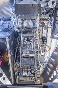
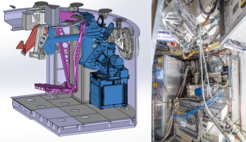
 CAD sketch of a cut-out of the APEX Cassegrain cabin with N3AR in blue; A-MKIDS M3 mirror and mountings in pink. (Right) Photo of N3AR during installation, still without mounted LOA (blue disk below the center of the photo is the protection cover of the RF window).")
Contrary to APEX' other receivers, N3AR does not use cooled mixers, e.g. SIS. It is based on cooled HEMT amplifiers and a first mixing-stage at ambient temperature. Because this makes the interiors of the cryostat quite simple, the complexity of the receiver is drastically reduced, making it more reliable, easier to use and maintain.
N3AR consists of four main parts: a cryostat; an “Upper Optics Assembly” (UOA); a “Lower Optics Assembly” (LOA) and an electronics rack, which also carries the cryostat (Fig. 1 and Fig. 2).
Cryostat: To shorten the development time, an already existing cryostat, which was primarily used for various lab tests, was adapted. It uses a Sumitomo RDK-415D cold head with ~1.5 W of cooling power at 4.2 K. The dewar windows consist of 5 mm HDPE with a 790 µm GoreTex layer one both sides to suppress reflections.
The „Upper Optics Assembly“ (UOA) is mounted to the Cassegrain cabin's ceiling and houses mainly the select-optics assembly to switch between single- and dual-color observations. The telescope beam either
- passes through the optics assembly unchanged, for observation with the A-cabin receivers (e.g. NFLASH or SEPIA;
- is redirected towards N3AR by a flat mirror (N3AR-only observations); or
- is split up using a high-pass dichroics filter, which was fabricated in our institute (dual-receiver observations with N3AR and either NFLASH-230 or SEPIA-345).
The "Lower Optics Assembly" (LOA) is fixed to the cryostat and has motorized mirrors to intercept the receiver beam and direct it towards the calibration loads.
Electronics rack: The cryostat is mounted on top of a 19” electronics rack, which is fixed to the Cassegrain cabin’s floor. The rack houses the support electronics to monitor and control the receiver, as well as the intermediate frequency (IF) processor and the backends.

Signal Chain
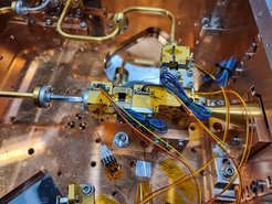
Inside the cryostat (Fig. 3), the corrugated feedhorn, from Radiometer Physics GmbH (RPG), is connected to an Boifort Orthomode-Transducer, made in-house, which splits the polarizations. The wave of each polarization is then amplified by two HEMTs (manufacturer: Low Noise Factory), separated by an isolator from MicroHarmonics. The amplified signals are afterwards directed out of the cryostat, into a down-converter system, also made by RPG. The RPG-system incorporates RF- and IF-hybrids to separate the sidebands. The down-converter generates four IF signals (1 per polarization and sideband) in the range of 2 – 20 GHz. Two of these outputs can directed to the VLBI digitizers. For spectroscopic observations, all four outputs are further processed by our modular IF processor (a copy of the NFLASH/SEPIA IF processor), which converts the (sub-)bands 4 – 8 GHz, 8 – 12 GHz and 12 – 16 GHz to 0 – 4 GHz baseband. Each baseband signal is finally digitized by our Fast-Fourier-Transform-Spectrometer cards with 64k channels.
Local oscillator (LO)
A synthesizer module from Virginia Diodes Inc. (VDI) operated between 9 and 13.25 GHz generates the LO driver signal, which is further multiplied by a Spaced AK-2X doubler and a quadrupler, integrated into the down-converter system. To suppress unwanted harmonics of the driver frequency, a tunable YIG-filter, by OmniYIG Inc., is placed between synthesizer module and doubler, as well as a bandpass filter (model: Marki FB-2250) between doubler and quadrupler.
Calibration
For calibrating the receiver gain, the well-known Y-factor methods can be used. The receiver system incorporates three calibration loads at different temperatures: cold-load at ~50 K; ambient-load at ~290 K; hotter-load at ~350 K. The "cold-load" is realized by "looking back" onto an absorber inside the cryostat. The "hotter-load" consists of a heated, temperature-controlled, absorber-coated cone. All loads are made in the institute.
Dichroics Filter for Dual-Receiver Observations

A major challenge was the development of the dichroics filter for simultaneous observations with N3AR and either NFLASH-230 or SEPIA-345. The filter had to be a high-pass filter, because of optical paths of NFLASH and SEPIA and space considerations in the Cassegrain cabin.

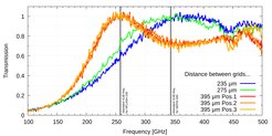
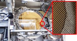
The final design (Fig. 4) is based on two free-standing wire grids. Each grid has horizontally and vertically oriented, 20 µm thick wires, with a spacing between two adjacent wires of 500 µm (i.e. they are cross-wired grid, see zoom-in in Fig. 4). The wires are winded in our institute onto circular frames with a free aperture of ~210 mm. The distance between the planes of the two cross-wired grids sets the frequency at which peak transmission occurs (Fig. 5). The distance is remote controllable in the range of 200 – 500 µm.
Reference Tone Generator for VLBI
For parallel VLBI observations with N3AR and either NFLASH-230 or SEPIA-345 a common phase reference signal is needed to measure the relative instrumental phase drift. A Schottky diode mixer (model: Pacific Millimeter WM) and a Microsemi AML618P2501 amplifier are used to generate a frequency comb. The comb is injected into the common optical path of the receivers in front of the dichroics filter. These phase calibrations tones are recorded along with the astronomical signal by the VLBI backends, and their phase variation with time is used to correct the astronomical data.