LAsMA – a 345 GHz 7-pixel array for APEX
The Large APEX sub-Millimetre Array is a 7-pixel heterodyne array receiver for APEX operating in the 870 μm atmospheric window. LAsMA is a MPIfR principal investigator (PI) instrument, developed – as with CHAMP+ and PI230 – for the APEX Nasmyth-B cabin.
It was successfully commissioned in APEX's winter shutdown 2016/2017.

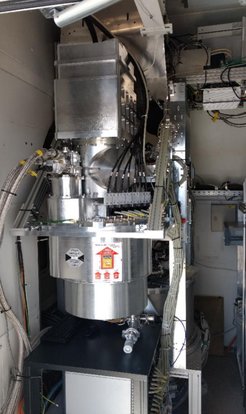
LAsMA installed in APEX's B-cabin.
| Overview | |
| Array geometry | Hexagonal, center pixel with 6 surrounding pixels |
| RF range | 268 – 375 GHz |
| Mixers | 7x 345 GHz 2SB SIS from IRAM |
| IF range | 7x 4 – 8 GHz, sideband-separated |
| Receiver noise temperature (SSB) | 80 – 100 K |
| LO | Solid-state AMC from VDIDriver synthesizer from Holzworth |
| LO distribution | Monolithic block, waveguide-based |
| Image de-rotator | K-mirror style |
| Frontend software | Fully remote controllable with auto-tuning procedure |
The array has a hexagonal arrangement on-sky with six pixels surrounding a center pixel. The full-width-half-power beam size lies between 17 and 23 arcsec (depending on observing frequency), with a spacing between pixels of 40 arcsec.
The receiver uses seven 345 GHz dual-sideband (2SB) Superconductor-Insulator-Superconductor (SIS) mixers developed at IRAM. Currently, they provide an intermediate frequency (IF) bandwidth of 4 – 8 GHz for each sideband.
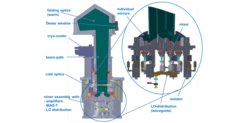
Each mixer is connected to a MMIC low-noise-amplifier (LNA) via an isolator to suppress back-reflections due to a possible impedance mismatch between mixer and LNA. Mixers and their biasing circuits, isolators and LNAs are integrated with the cold optics components on the 2nd cooling stage of the cryostat and cooled to approx. 4K.

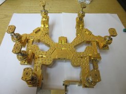
Monolithic waveguide-based LO distributor. The input is at the center of the block, the eight outputs at the end of the arms.
The local oscillator (LO) is based on an amplifier-multiplier chain (AMC) manufactured by Virginia Diodes, Inc. (VDI), tunable to output frequencies between 275 and 375 GHz. The last multiplier stage of the chain is located inside the LASMA cryostat and cooled to approx. 100K to increase the output power.
The LO distribution from the AMC to the individual LO ports of the mixers is purely waveguide-based. The splitting and guiding of the LO signal is done in a monolithic waveguide block with one input and eight output ports. The block incorporates seven branch-line hybrid couplers and was manufactured in our in-house workshop. The unused 8th output port is terminated by an in-house made waveguide terminator.
To compensate for image rotation on-sky, a K-mirror type image de-rotator is integrated into the warm optics. The optics design allows to install an additional wire grid as a polarization splitter to make the second – currently unused – polarization of the telescope beam accessible for future upgrades (1). Due to the limited space available inside the B-cabin and the – at the time of design – already operational CHAMP+ receiver, LAsMA's warm optics share components with CHAMP+'s optical setup.
For biasing the LAsMA mixers, we use a 14-channel electronics based on our modular BIAS concept.
All receivers in the B-cabin share the same IF processor and Fast-Fourier-Transform spectrometers, both developed in-house: the former by our group, the latter by the Digital Signalprocessing group.
IF processor and FFT spectrometers were designed to process an instantaneous bandwidth of 4 – 12 GHz; LAsMA's LNAs and isolators were chosen appropriately. Currently, the used IF hybrids limit LAsMA's IF bandwidth to 4 – 8 GHz. Future upgrades aim – in a first step – for a replacement of the current hybrids, and – finally – for a removal of the IF hybrids and using novel digital sideband suppression methods, implemented within the FFT spectrometers, to extend the IF bandwidth to 8 GHz.

(1) A new heterodyne receiver operating around 1 THz and using the 2nd polarization of LAsMA's optics path is already in an advanced design phase.