Technology
General layout

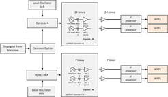
General layout of upGREAT.
The general layout of upGREAT is illustrated in the following schematic.
The signal from the telescope tertiary mirror passes through the Nasmyth tube and is split within the common optics via a frequency selective dichroic between the low frequency and the high frequency arrays.
On the optics plates, the signal beams are combined with their respective local oscillator (LO) beams using beam splitters, transformed to match the horn parameters of the Hot-Electron-Bolometer (HEB) mixers and directed into the cryostats towards the mixers.
The intermediate frequency (IF) output signal of the mixers is amplified by a LNA and the IF processor, before it reaches the spectrometers, developed by the Digital Signal Processing Group. The IF processor is a directly amplifying and filtering chain, which does not include any mixing process.
Please have a look at the references at the end of this page for more details about the upGREAT channels. Short summaries about individual components can be found in the following sections.
Cryostat

The upGREAT cryostats are built by CryoVac - low temperature technology - GmbH und Co. KG, Troisdorf, Germany, and integrate closed-cycle coolers, which are custom modified Pulse Tube (PT) coolers – type PTD-406C – from TransMIT GmbH in Giessen, Germany. These pulse tube coolers are suitable for this project as they can operate with ± 45° tilt angles.
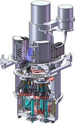
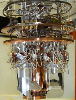
The interior of the LFA and HFA cryostat is – except for small deviations – identical. The cryostats are equipped with thermal shields connected to the 1st and 2nd stage of the PT cooler. The mixers, LNAs and optics related to a 7-pixel sub-array form a unique structure, named cold tower, on the cold plate of the 2nd stage (at ~4 K). The LFA cryostat thus houses two of these cold towers (see photo), while the HFA cryostat has only one installed. Nevertheless, it can be easily equipped with the second tower in the future.
The RF windows at the bottom of the cryostats are made from 525 µm thick high-resistivity Silicon with etched linear grooves on both sides to act as matching layers at the wavelengths of interest.
The LFA cryostat uses one layer of Zitex G-104 cooled to 40 K (mounted on the 1st stage shield) as IR filter. The IR filter inside the HFA cryostat (an 8 THz low pass filter from Tydex, LLC) was removed, because tests showed that cooling power was sufficiently high to keep low enough temperatures without the filter. The loss of the filter at 4.7 THz amounted to ~ 7%.
SOFIA’s cryocooler system utilizes two liquid-cooled He compressors, manufactured by CryoMech. For lab operation in the hangar, two air-cooled He compressors from Sumitomo Heavy Industries, Ltd. are used.
| LFA | HFA | |
| Pulse tube | TransMIT PTD-406C | |
| Lab compressor type | CSA-71A | CSA-31C |
| Compressor power consumption with 50 Hz supply | 6.5 kW | 3.4 kW |
| Cooling power at 4.2 K | 0.84 W | 0.53 W |
| Tilting impact on cooling power at 4.2 K | 10 % degradation | |

Mixers
The upGREAT channels are equipped with state-of-the-art HEB mixers, fabricated at KOSMA [3][4]. They are waveguide-based NbN devices on Si membranes. The mixers provide an intermediate frequency bandwidth of 0.1 – 4 GHz. The mixer horns are scaled versions of a smooth-wall spline horn from [5], and were manufactured by Radiometer Physics GmbH, Meckenheim.
Local oscillators
The LFA uses two amplifier-multiplier chains (AMC) – one for each 7-pixel sub-array – from Virginia Diodes, Inc., driven by compact synthesizer from the same company. These solid-state local oscillators have limited relative bandwidths. Currently, the available RF frequency range extends from 1.83 to 2.07 THz. In parallel to VDI’s efforts of increasing the power and bandwidth of the AMCs, the Sub-mm Technology division is developing photonic-mixer local oscillators. Please refer to the TeraHertz Technology section for more information.
For the HFA, two local oscillators based on quantum-cascade lasers (QCL), developed by two groups (DLR-Pf and KOSMA), are available. The QCL from DLR-Pf is an improved version of the QCL-LO used for the GREAT-H channel [7], the 4.7 THz single-pixel predecessor of the HFA. The KOSMA QCL-LO is a new development relying on a QCL chip fabricated by the ETH Zurich.
Optics
The signal beam coming from the telescope passes through a rotatable K-mirror assembly acting as a de-rotator. This de-rotator allows to set the array orientation on sky, and to compensate for the sky rotation in the instrument focal plane. Afterwards a 3.3 THz low pass dichroic filter, manufactured by QMC, splits the beam between the low and high frequency arrays.
The design of the warm and cold optics of the upGREAT channels is based on two Gaussian beam telescopes (GBT), common to all pixels of a 7-pixel sub-array, and a parabolic mirror in front of each mixer. The first GBT is formed by two ellipsoidal mirrors on the warm optics plate. The second GBT consists of another mirror on the plate and a cooled mirror inside the cryostat.
The LFA mirrors are aluminum units milled on the ultra-precise Kern milling machine of the institute’s workshop. The estimated surface accuracy is a few µm RMS. The HFA optics use commercially manufactured gold-plated mirrors with a specified accuracy of ~ 10 nm, made by Kugler GmbH.
The coupling of LO and signal beams is done via beam splitters within the second GBT. The LFA optics make use of a wire grid, fabricated in our division, while the HFA optics incorporate a 3.5 µm thick Mylar foil.
References
- Risacher et al., ITTST 2016
- Risacher et al., A&A 2016
- Risacher et al., JAI 2018
- Pütz et al., 2012
- Büchel et al., 2015
- Granet et al., 2004
- Richter et al., ITTST 2015