Technology


General
4GREAT is a receiver system designed for the modular GREAT platform. GREAT can be equipped with two GREAT-channels simultaneously. The 4GREAT channel consists of four main components: the 4GREAT cryostat, an optics plate, the upper local oscillator unit (LO-U), and the lower local oscillator unit (LO-D).
In parallel to 4GREAT, the upGREAT/HFA channel can be operated.
Cryostat


4GREAT is based on an upGREAT-type cryostat (refer to the upGREAT webpages for details). Similar to the cryostat interior of the upGREAT channels, each mixer, its connected low-noise amplifier (LNA), its biasing circuitry, and the cold part of its optics form a tower-like structure, named cold-tower, on the 2nd stage plate (cooled to 4 K). The cold towers of 4G-1 and 4G-2 incorporate additional ferrite isolators between mixer and LNA to suppress reflections.
Further IF amplifiers and biasing electronics (both at ambient temperature) for each receiver are mounted on the outside, on top of the cryostat.
Mixers
4G-1 integrates a spare flight mixer from HIFI band 1, provided by LERMA (France). 4G-2 uses a spare device for HIFI band 4, provided by SRON (Netherlands). These mixers are Superconductor-Insulator-Superconductor (SIS) devices. 4G-3 and 4G-4 make use of the Hot-Electron-Bolometer mixers from KOSMA, formerly used in GREAT-L1 and GREAT-M [2]. All mixers, regardless of their technology, are DSB. The SIS have an intermediate frequency (IF) of 4 – 8 GHz, whereas the HEB’s output IF signal is in the range of 0 – 4 GHz.
")

Local oscillators
The placement of four local oscillator systems within the GREAT structure posed a challenge. Because of space limitations in the original LO compartment in the lower part of the GREAT structure, the LO systems of 4G-1 and 4G-2 were put into an additional housing which is installed at an auxiliary vacuum port to the optics compartment located between telescope flange and 4GREAT cryostat.
All LO systems use amplifier-multiplier-chains (AMC) from Virginia Diodes Inc., connected to compact driver synthesizers of the same company. The synthesizers are mounted in a 19” box within the electronics rack of the GREAT structure. Given the relatively wide frequency coverage of the four 4GREAT sub-channels some of these AMCs are composed of two sub-chains.
The coupling of LO beams and signal beams is done using wire grids, produced in-house, for 4G-1, 4G-2 and 4G-3. The optics of 4G-4 incorporate a Martin-Puplett-Diplexer, since the LO output power is too low (< 4 µW) for a beam splitter. The wire grids and diplexer are placed directly before the beams enter the cryostat.
Optics

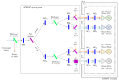
The main part of the 4GREAT optics (the warm part) is mounted on an optics plate which is placed below the cryostat inside the GREAT structure. A smaller part (the cooled elements of the optics) resides inside the cryostat. The figure shows a schematic of the optics layout.
The 4GREAT channel is flown in combination with the upGREAT/HFA channel. A 3.3 THz low-pass dichroic filter is used to extract the signal beam of HFA from the telescope beam. The remaining 4GREAT signal beam is further split, first by polarization using a wire grid and later by dichroic filters to finally create the four signal beams of the 4GREAT sub-channels.
The design of the optics is purely reflective with aluminum mirrors. Each of the four optical paths incorporates two Gaussian Beam Telescopes (GBT) and a final parabolic mirror in front of the mixers – the design is analog to the optics design of the upGREAT channels. Each of the sub-channel’s signal optics is made up of the same kind of elements, but dimensioned for their respective frequency ranges. Some of these elements are common to two or even all of the channels. The 4G-4 optics has additional components, mainly because of the diplexer.
References
- Duran et al., 2020, in prep.
- Heyminck et al., A&A 2012