Development of the APEX FFTS
The rapid increase in the sampling rate of commercially available analog-to-digital converters (ADCs) and the increasing power of field programmable gate arrays (FPGAs) chips has led to the possibility to directly digitize the down-converted intermediate frequency (IF) signals of coherent radio-receivers, and to transform the digital signal into a spectrum in real-time. Based on the technological progress and the experiences gained in building a narrow-band FFTS (Stanko, 2005) the APEX FFTS was developed by the MPIfR Digital Group.
FFTS: Hardware
The APEX FFTS is based on the currently most powerful digitizer/analyzer board available from Acqiris, Switzerland. It incorporates two 1 GS/s ADCs which feed a XILINX Virtex 2 Pro70 FPGA chip. By combining both ADCs in an interleave manner (180 deg phase-shift), the board is capable to sample an analog input signal at 2 GHz clock rate which results in a 1 GHz Nyquist bandwidth. For a more detailed description of the FFTS hardware, especially the AC240 Board, we refer to (Benz, 2005) and the Acqiris documentation.
FFTS: Signal processing pipeline
The digital signal conversion from the time domain to an integrated power spectrum is done in only one complex FPGA chip. The spectrometer core development was contracted to RF Engines Ltd. (RFEL), following our guidelines, and finally integrated at MPIfR. The core is based on RFEL's HyperSpeed Fast Fourier Transform (FFT) technology. It receives 8-bit samples from the two ADCs at a continuous sample rate of 2 GHz, and then processes this data in a sequence of four steps, as indicated in the flow of Figure 1.

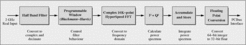
First, a Digital Half Band Filter (DHBF) converts samples to a complex I/Q-format, and reduces the sample rate by a factor of two (decimation), which eases the subsequent processing requirements. A useful side effect of the DHBF is its ability to reduce the level on both bandpass sides. Indeed, this limits the useable bandwidth to ~900 MHz but has the great advantage of decreasing aliasing effects caused by real analog filters with finite stop band rejection. The DHBF is followed by the application of a windowing function, which weights the data in order to control the filtering performance of the FFT. The coefficients are user programmable at run-time, allowing the performance characteristics of the spectrometer to be modified for changing operational scenarios. For a high resolution and high dynamic-range spectrometer a 3-term Blackman-Harris window is a good compromise between sidelobe reduction, sidelobe fall-off and main lobe widening. For a comprehensive discussion about window functions and there properties, the interested reader can refer to (Nuttall, 1981). The 16K-point HyperSpeed FFT core from RFEL forms the central element of the system, performing the conversion from the time-domain to the frequency-domain, and it includes bit reversing to sort the data in natural frequency order. The FFT is built using a highly parallel architecture in order to achieve the very high data rate of 2 GBytes/s. The final step of processing contains the conversion of the frequency spectrum to a power representation, and successive accumulation of these results. This accumulation step has the effect of averaging a number of power spectra, thereby reducing the background noise and improving the detection of weak signals. This step also reduces the huge amount of data produced by the earlier stages, and eases any subsequent interface bandwidth requirements and processing loads. The output from the spectrometer core is in a 32-bit floating-point format. With an ordinary PC for further data-managing and data transfer, the FFTS is integrated into the APEX control network and interfaces with the control system APECS via SCPI commands, as described in (Muders, 2006).
FFTS: Frequency resolution
To understand the spectral resolution and effective channel bandwidth of the FFTS, the spectral leakage caused by the application of the Fourier Transform (FFT) to a noisy signal must be considered. Spectral leakage is the result of the assumption in the FFT algorithm that the signals are contained in a single FFT time record, and thus periodic at intervals corresponding to the length of this time record. If the time record has a non-integral number of cycles, this assumption is violated and spectral leakage occurs, which introduces a wide range of frequencies in the frequency domain and in consequence the energy of a signal is spread to adjacent frequency bins (Harris, 1978). If no window function is applied prior to the FFT, the first side lobes are attenuated by 13 dB relative to the main lobe and the side lobe fall-off rate is 6 dB per octave. Consequently, the selectivity of a bare FFT is poor, which results in a large amount of ripples in the passband. In addition, the spectral leakage from a large signal component may be so severe that other weaker signals at different frequencies are masked. The effects of spectral leakage can be restricted by reducing the discontinuities at both ends of the time record, i.e. by multiplying the data with a suitable window function. For radioastronomical applications a Blackman-Harris window is adequate due to its excellent spectral leakage attenuation and good amplitude conservation for random and noisy input signals.
The APEX FFTS applies a 3-term Blackman-Harris window
![]()
.
Unfortunately, there is always a trade-off between the main lobe width and the side lobe leakage: As the side lobe level decreases, the main lobe width is increased. To characterize this behaviour the equivalent noise bandwidth (ENBW) can be used. The ENBW indicates the equivalent rectangular bandwidth of a filter with the same peak gain that would result in the same output noise power. Table 1 is a comparison of the properties of a rectangular and a Blackman-Harris window. Since the ENBW for a rectangle filter is 1.0, which is equal to the channel separation frequency (61.035 kHz), the frequency resolution for the APEX FFTS, applying the Blackman-Harris window, is 98.267 kHz.
| Window function | Highest side lobe | Fall-off rate | 6 dB bandwidth (bins) | ENBW (bins) |
| Rectangle | -13 dB | -6 dB/oct | 1.21 | 1.00 |
| Blackman-Harris | -61 dB | -6 dB/oct | 2.19 | 1.61 |
Table 1: Rectangular vs. Blackman-Harris window function
FFTS: IF processor
Interfacing to the FFTS, an IF processor has been developed which is capable of down-converting the APEX-IF (4-8 GHz) to baseband (0-1 GHz). The system contains two identical IF chains for simultaneous observations with two receivers. An input multiplexer allows to connect each of the IF chains to six receiver outputs, providing the opportunity for fast switching between different receivers. In addition, it is feasible to connect one receiver to both FFTS with different IF offsets, thus providing effective bandwidths broader than 1 GHz and up to 2 GHz, depending on the overlap area (see sect. 5). To ensure an optimal input to the FFTS an autoleveling algorithm is implemented in the IF processor. The complete system is both, fully manually and remote controllable using the SCPI command interface (Muders, 2006).