Local Oscillator Optic

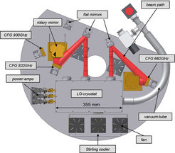
The design of the LO chains follows the experience gained during the development of the Herschel/HIFI Local Oscillators. A synthesizer signal in the range of 11 – 18 GHz is first multiplied by a factor of 6 to generate 1 mW RF power at the input of the W-band power amplifier provided by JPL. The amplifier produces up to 250 mW of RF signal power and drives the cascaded tuner-less frequency multiplier stages which are cooled to 120K. In the 450 μm channel a doubler/doubler/doubler combination is used, whereas a doubler/doubler/tripler cascade generates the output in the 350 μm channel. To cover the wide tuning range of the 350 μm channel, two LO-chains are necessary. A rotary mirror selects between these two LO signals (upper figure). All three LO-chains are operated cold (<120 K) to improve the performance as well as the lifetime of the multipliers. Cooling is provided by a commercial Stirling-cooler with ≈ 9 W cooling power at 80 K. The warm air from the Stirling-cooler is directed towards the dewar windows to prevent condensation.
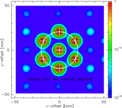
A critical requirement for building a heterodyne focal-plane array is the equal distribution of the LO-signal to each individual mixer. For frequencies above 500 GHz this can be achieved by quasi-optical LO-coupling only. Submillimeter phase gratings have been developed for this purpose and were successfully applied. They need a flat phase distribution to work properly, which is ensured by imaging optical elements within the LO beam path. For CHAMP+ we decided to use so-called collimating Fourier-gratings (CFG) as LO beam divider. At the reflection point of a parabolic mirror the phase distribution of a Gaussian beam is flat. CFGs combine a parabolic mirror with a phase grating by superimposing the grating structure onto the mirror surface. The advantage is a rather simple optics layout for the LO distribution scheme with, of course, a high efficiency of the beam divider (> 70% for this special diffraction pattern, which means that > 10% of the injected LO power is finally directed to each of the seven mixers). The usable bandwidth is of the order of ±8% with respect to the design frequency.

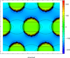
Grating structure of the CFG. Units are in degree, contours are in steps of 15°.