Signal Optic

For a dual-frequency receiver the prime optical design requirement is to optimally match both frequency channels simultaneously to the telescope. The optical interface to the telescope in the focal plane is nearly frequency independent. The optics of CHAMP+ follows a Gaussian telescope set-up, which provides both, linear scaling of the beam-sizes and frequency-independent waist-positions. The tertiary mirror (M1) in the Cassegrain cabin and the first mirror (M2), located already inside the Nasmyth cabin, form a Gaussian telescope with a magnification factor 3168/662 = 4.78. Between the two mirrors the signal passes the elevation bearing. The most critical design driver (in order not to taper the off-axis beams) has been the limited aperture of the elevation tube (the clear aperture is only ≈350 mm in diameter). After the flat folding mirror, M3 and a HDPE-lens (already inside the cryostat) form a second Gaussian telescope (with a magnification of 826/413 = 2), which serves to minimize the mechanical size of the cold optics and to gain additional path length for the SSB-filters and the diplexer optics.
. The arrangement of the individual optical components and the resulting beam path is visualized.")

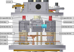
Between mirror M3 and the HDPE-lens the signal passes the dewar window and a cross-wire grid to separate the two linear polarizations. Each polarization is associated with one of the two colors (660 GHz and 850 GHz, respectively) of the array and therefore allows simultaneous observations with both sub-arrays. A Martin-Puplett interferometer, used as SSB-filter, follows in both paths (see figure for more details). The image bands of these filters are terminated on a 15 K absorber cone. The LO-signals are injected with a polarizer grid and finally combined with the astronomical signal using a second Martin-Puplett interferometer as diplexer. In a last step a so-called fly’s-eye lens, combining seven individual lenses in one piece, matches the common optics to the individual horn antennas of the array.
Between mirror M3 and the HDPE-lens the signal passes the dewar window and a cross-wire grid to separate the two linear polarizations. Each polarization is associated with one of the two colors of the array and therefore allows simultaneous observations with both sub-arrays. A Martin-Puplett interferometer, used as SSB-filter, follows in both paths (see figure for more details). The image bands of these filters are terminated on a 20 K absorber cone. The LO-signals are injected with a polarizer grid and finally combined with the astronomical signal using a second Martin-Puplett interferometer as diplexer. In a last step a so-called fly’s-eye lens, combining seven individual lenses in one piece, matches the common optics to the individual horn antennas of the array.
Simulations of the complete optics, solving the Maxwell-equations numerically at the mirror surfaces, show a coupling efficiency to the Gaussian fundamental mode for the – most critical – off-axis beams ≥ 97%.